No AI Generated Content
SFD & BMD Analysis of Beam
Get Free Samples Written by our Top-Notch Subject Experts For Taking Online Assignment Help
1.0 Objectives
The main objective of this report is to analyse the shear force and bending moment diagram on the structure of the beam. The dimensions of the beam are needed to be evaluated that is used for analysis. The external loads with supports are needed to be identified in the beam structure. The shear force and bending moment diagram are needed to be drawn of the beam. The elastic bending stress distribution is needed to be calculated that will be used for evaluating the critical section in the beam. The shear stress distribution will also be calculated for the beam structure. The maximum deflection is needed to be calculated of the beam structure.
2.0 Background and Introduction
The SFD and BMD are essential to analyse the bridge and building structure. The shear force and bending moment diagram are used to analyse the stress distribution and bending moment distribution on the beam. This analysis is done in the initial phase of design because this helps in creating the actual model of the beam in bridge after analysing the critical value of stress and moment in that beam. This design helps in performing the structural design of the bridge and building structures. This model helps in determining the size, material and type of beam structure that is to be used in the design of structures in the real world. This analysis is used to analyze the types of loads acting on the beam and creating out a design that will not cause any structural failure in the body. This diagram also helps in analyzing the deflection of the beam in the structure with the help of the elastic curve method and Macaulay’s method.

3.0 Methodology
Now considering a beam structure that is motley used as truss members in any bridge. The beam is of specified length and dimension.

Figure 1: Simply supported beam
(Source: https://civilmint.com/what-is-simply-supported-beam/)
The above figure is of beam structure which is simply supported at its two ends. These types of beams are used as the members of the bridge structure. The structure of the bridge is made of several beams of the same type that is connected with each other at the joints. The force is applied to the beam structure due to the mobility of vehicle goods on the bridge. All the forces are incurred by this type of member so it is essential to design the beam structure with the beam structure taking into account the critical stress and critical bending moment analyzed during the analysis of SFD and BMD of the beam in the initial phase.
The above beam structure is of an overall length of 6m. It is simply supported at it its two end A and B. The supports at A and B are RA and RB.
The point load of 3kN and 6kN are acting on the beam at points C and D respectively.
Length of each section are defined below -
AB = 6m
AC = 2m
AD = 4m
CD = 2m
For evaluating the reactions at RA and RB, applying force balance and moment balance method on the beam.
From the force balance method,
RA + RB = 3 + 6 = 9kN — 1
Now applying moment about point A,
∑MA = 0
RB ? 6 - 6 ? 4 - 3 ? 2 = 0
Here taking positive moment value for clockwise directions and negative moment value for anticlockwise direction.
By solving the above equation,
RB = 5kN
Now putting the value of RB in equation 1, the value of RA will be 4kN.
Shear force diagram calculations (SFD)
Now calculating the shear force in the beam,
Value of Shear force at A, SFA= +RA = 4kN
Value of Shear force at C, SFC = 4 - 3 = 1kN
Here taking positive force value in upwards direction and negative force value in the downward direction.
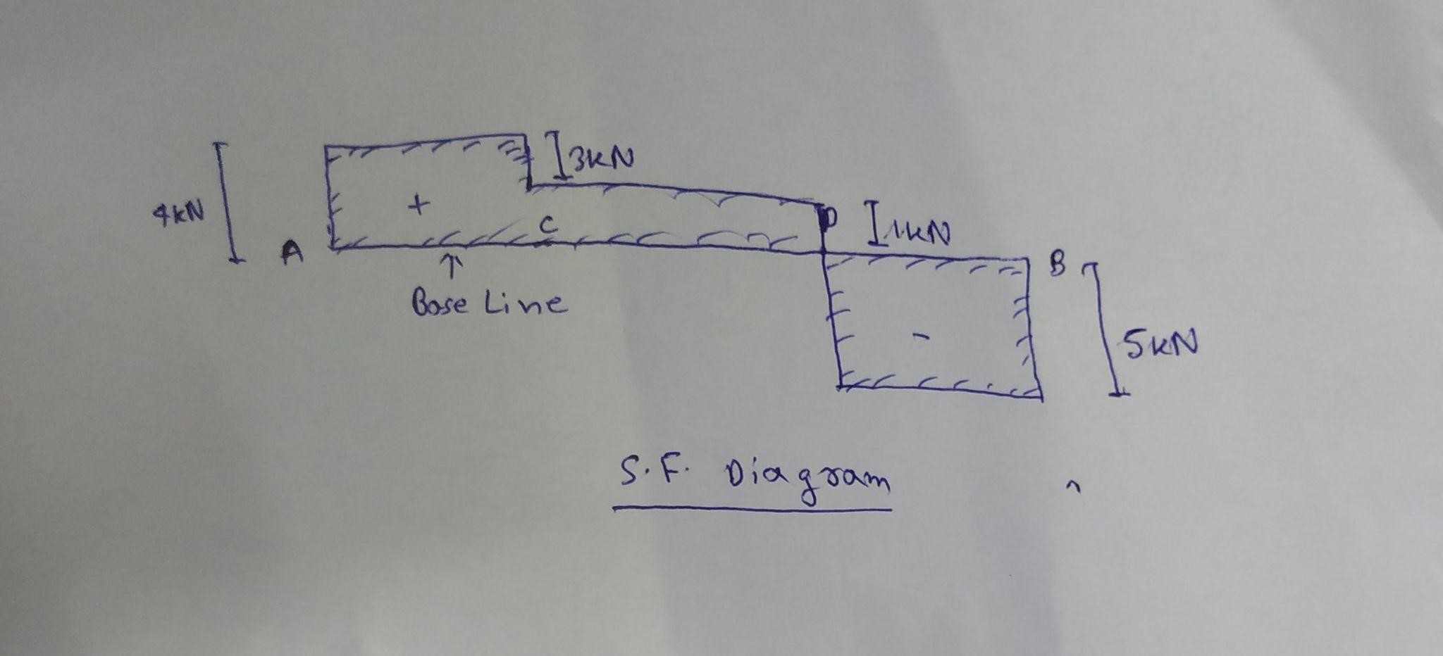
The SF between A and C is constant that is 4kN.
The SF between C and D is also constant that is 1kN.
SF value at D, SFD = 1-6 = -5kN
The SF between D and B is equal to -5kN ie; the force is acting in the downward direction.
SF at B, SFB = -5kN
The below figure shows the shear force diagram (SFD) of the beam structure.

Figure 2: Shear force diagram
(Source: Hand written)
Bending moment diagram (BMD)
Bending moment diagram calculations are given below-
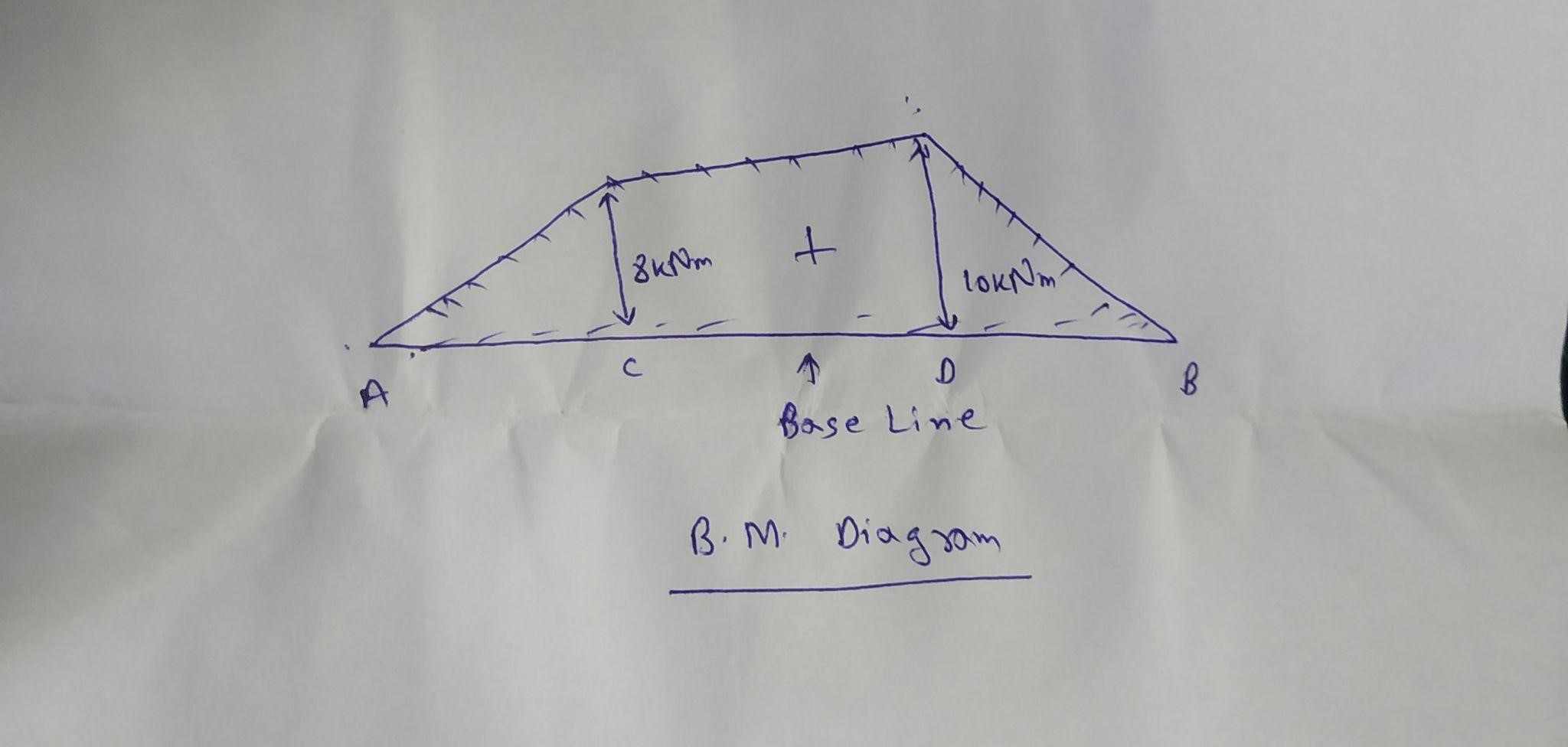
Bending moment at A = 0,
Bending moment at C = RA ? 2 = 4 ? 2 = 8kNm
Bending moment at D = RA ? 4 - 3 ? 2 = 10kNm
Bending moment at B = 0
The bending moment diagram is given below.

Figure 3: Bending moment diagram
(Source: Hand written)
The critical sections of this beam structure are “A, B, C and D” at which the force is acting on the beam structure.
The value of shear force and bending moment at each point is described below -
SFA = 4kN
SFC = 1kN
SFD = -5kN
SFB = -5kN
The above is of shear force evaluated at each point.
BMA = 0
BMC = 8kNm
BMD = 10kNm
BMB = 0
Now using Macaulay’s method of deformation, the maximum deflection is given by,


